Uk:Roof modelling
Як малювати будівлі в Потлач 2 з використанням супутникових світлин BING.
Ця стаття стосується використання Потлач 2 та BING. Крім окремих порад, які стосуються безпосередньо Потлач 2 та BING, ця стаття також згодиться для:
-інших редакторів, накшалт JOSM чи Merkaartor
-інших супутникових світлин та світлин, отриманих з літальних апаратів.
- Автор: Marek Strassenburg-Kleciak
Поради
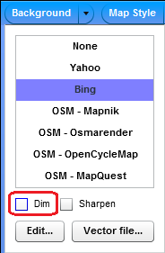
Для малювання будівель використовуйте найдетальніший рівень масштабування. У Потлач 2 шар фонових зображень не повинен бути приглушеним сірим кольором, бо це ускладнює малювання. Щоби вимкнути те приглушення виберіть Фон (Background) та приберіть прапорець з «Приглушити» («Dim»):
Малювання будинків з простим контуром
Мета цієї статті — навчити вас малювати контури будівель якомога точніше:
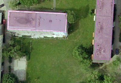
Щоби зрозуміти запропонований підхід до нанесення будівель, подивіться на ці шматочки супутникових світлин:
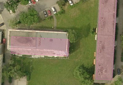
Після того, як намалюєте контур даху за пропонованою методикою, слід посунути намальоване до позиції на рівні землі. Щоби зробити це, посуньте намальовану лінію контуру до того кута будівлі (на фото це нижній лівий куток), якій найліпше видно (на фото це білий контур), звідки падає тінь:
Про те, як будуються будівлі
Найчастіше будівлі проектуються та зводяться як споруди з прямими кутами. Паралельні та перпендикулярні стіни простіші та дешевші у будівництві, їх застосування дозволяє стандартизувати складові та спростити процес будівництва (теж саме стосується й дахів). Вони також є зручними для мешканців, які можуть розмістити свої прямокутні меблі по прямих кутах. Але не всі будинки побудовані з використанням прямокутного планування. Прикладом можуть бути старі будинки різноманітних форм, які виникли через примхи архітекторів, що намагалися уникати прямих кутів для більш вражаючого візуального ефекту фасадів, або через обмеження, які накладаються оточенням: кутові будинки на розі вулиць, що перетинаються не під прямим кутом.
Таким чином, під час креслення по аерофотознімках з поганою роздільною здатністю, треба оцінити: чи має будинок прямі кути при землі, чи можливо вони такими не є. Знання історії населених пунктів та архітектурного стилю можуть стати у нагоді для оцінки поточного стану речей.
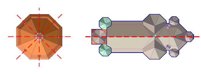
Будь ласка, зверніть увагу: будівлі часто мають вісі симетрії!
4x та 2x бічна симетрія
Як зробити кути прямими
Потлач 2 має вбудовану функцію, яка робить кути замкненого багатокутника прямими. Для будівель з порівняно простими формами ця функція дає цілком пристойний результат. Навіть з будівлями з багатьма прямими кутами:
Аналогічну функцію має редактор JOSM. Намалюйте замкнений контур будівлі, виділіть цей контур мишею (для виділення контуру клацніть мишею на одному з його відрізків, але не на точки контуру!) та натисніть клавішу Q.
Хитрощі
A. Креслення декількох однакових будівель.
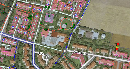
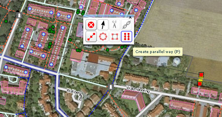
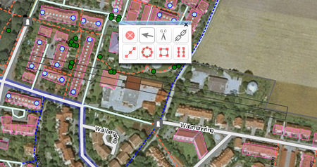
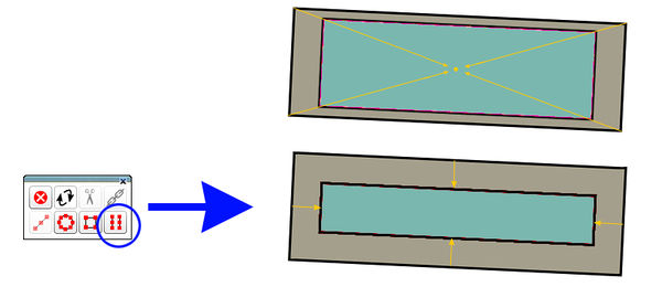
Потлач 2 ще не має функції "копіювати-вставити", але ви можете зробити так: скористайтесь функцією «створити паралельні лінії» та зробіть копію вже накресленого контуру будівлі. Якщо істотно наблизитись до будівлі, ви зможете створити копіюю, що майже не відрізнятиметеся від оригіналу. В багатьох населених пунктах ви можете побачити будинки з майже ідентичною геометрією, що стоять паралельно друг до друга. Якщо якості супутникового знімку не достатньо, ви можете обкреслити якомога точніше будівлю, яку видно краще за інші та використовувати її як зразок.
B. Креслення будівель з дуже складною геометрією.
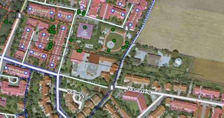
Потлач 2 досі не має розширених функцій для автоматизованого проектування. Але ви можете створити гарний шаблон для дуже точного відтворення контуру будинку за допомогою створення багатьох допоміжних ліній (за допомогою команди «створення паралельних ліній», клавіша «P»):
Використання: Нам треба накреслити лінію контуру по самих крайніх точках будівлі та перетворити її на прямокутник (інструмент «зробити кути прямими»). Потрібно копіювати прямокутники стільки раз, скільки це буде потрібно для створення всіх допоміжних ліній (які відповідно будуть паралельним та перпендикулярними). Допоміжні лінії (прямокутник) потрібно пересувати до зовнішніх країв поверхні даху, щоб мати змогу відтворити форму будівлі:
Після того, як ми обкреслимо контур будівлі, допоміжні лінії потрібно вилучити…
Результат
Для спрощення креслення будинків в JOSM використовується втулок Buildings_tools. Ознайомтесь з описом того як креслити будинки складної форми в JOSM.
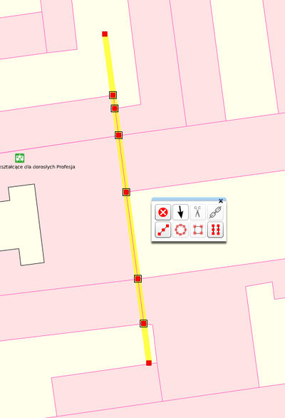
B.2. «Вирівнювання» сусідніх зовнішніх стін будинків з використанням команди: «випрямити лінію»
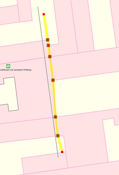
Ситуація: Маємо кілька будинків, що стоять впритул друг до друга (як на цьому прикладі, старі будинки в центрі міста). Ми можемо побачити (або знаємо), що насправді зовнішні стіни будинків знаходяться на одній лінії, але на мапі маємо «майже пряму лінію». Для вирівнювання ми накреслимо допоміжну лінію, що проходитиме через всі спільні точки. Треба щоб хоча б одна кінцева точка цієї лінії знаходилась за межами стін, які нам потрібно вирівняти:
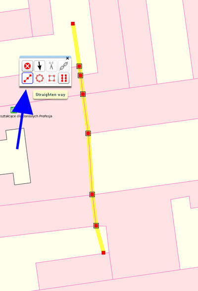
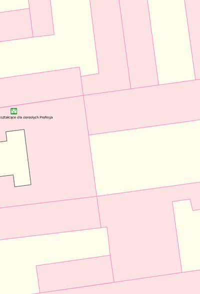
Скористайтесь інструментом: "спрямити лінію". В результаті ми отримаємо стіни всіх будинків на одній лінії.
Будинки після застосування інструменту: "спрямити лінію"
Після вилучення допоміжної лінії:
C. Креслення довгих «змієподібних» будинків в Потлатч 2
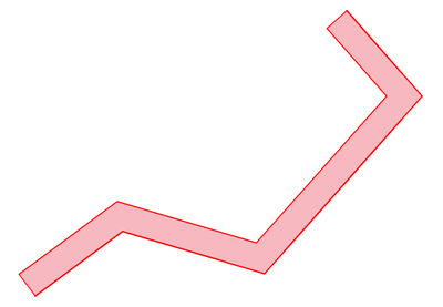
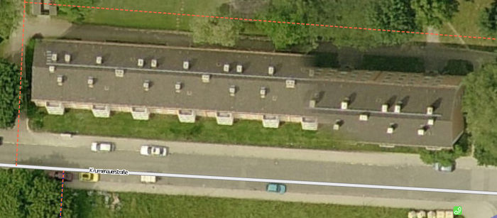
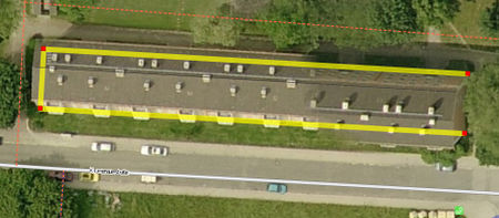
Креслення довгих багатоповерхових будинків, що кілька разів змінюють свій напрямок часто є джерелом неточностей:
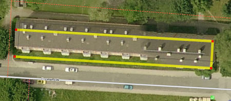
Часто мапери встановлюють такий масштаб, щоб було видно весь будинок на екрані і креслять його контур, що значно впливає на точність. Особливо важко накреслити прямі кути на коротких сторонах будинку.
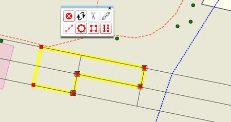
З цим можна впоратись використовуючи інструмент для креслення паралельних ліній в Потлатч 2:
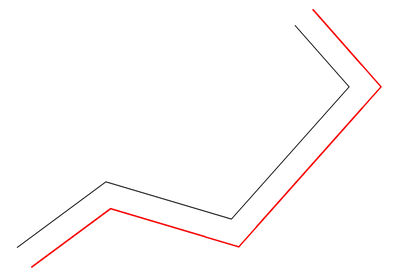
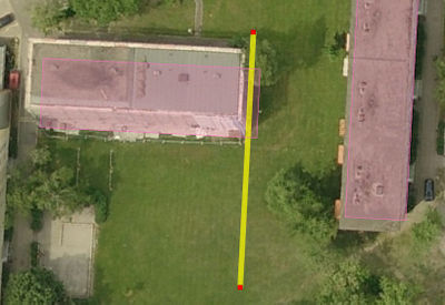
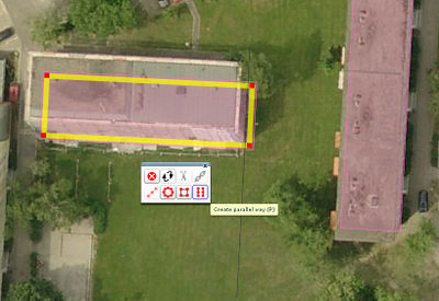
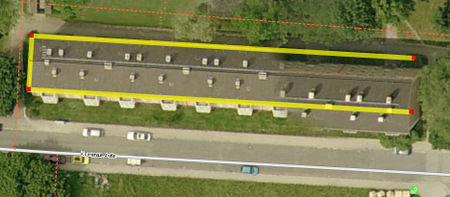
Потрібно якнайкраще накреслити лінію вздовж довгої сторони будинку, а потім створити паралельну лінію скориставшись інструментом: "створити паралельну лінію", (або натиснути P).
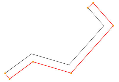
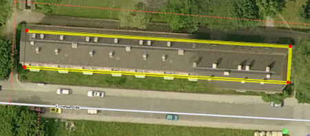
Ми отримаємо другу лінію, що буде паралельної до першої. Але найголовніше, коли ми з’єднаємо ці дві лінії ми отримаємо прямі кути на коротких сторонах. Потім натисніть ’Ctrl' і виділіть обидві лінії.
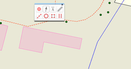
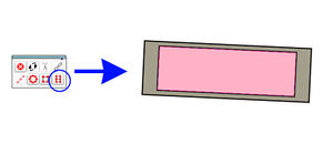
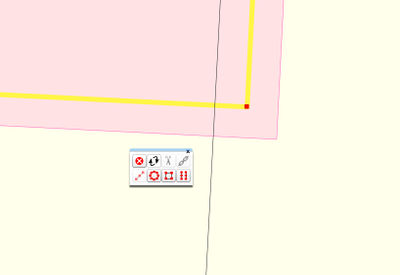
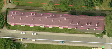
Після чого клацніть на кнопку «з’єднати лінії» ![]() і обидві наші лінії з’єднаються в одну замкнену лінію, утворивши контур будинку:
і обидві наші лінії з’єднаються в одну замкнену лінію, утворивши контур будинку:
Типові помилки під час моделювання геометрії даху за допомогою аерофото
Контур в невідповідному місці
Мапер дуже точно накреслив контур будівлі,
але змістив лінію не туди, обравши помилковий кут звідки падає тінь від будівлі. (Це доволі розповсюджена помилка.)
Контур потрібно посунути так, щоб він знаходився саме там, де фундамент на поверхні, як на малюнку:
Неправильна інтерпретація двоскатного даху
Коли дах є доволі гострим, іноді ми можемо бачити під певним кутом лише половину кутів будівлі. Тим не менш стіни є рівними — цей кут, що ми бачимо не є частиною контуру будинку.
Неправильна інтерпретація даху з одним скатом
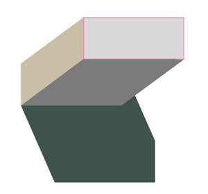
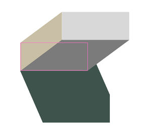
Дах з нахилом може бути складним навіть для досвідчених маперів, тому що нахил даху може легко залишитися непоміченим. Якщо таке трапляється, контур будинку виглядатиме так:
If one is not carefull and just selects the "make rectangular" function, the result looks like this:
Quite often this error is only evident only after the previous step, when the edge of the now oblong building shape, and the corresponding edge of the shadow aren't paraller - assuming the mapper is lucky enough to see the edge of the shadow well enough.
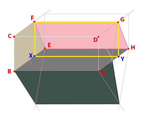
Correct procedure:
- First draw the both visible edges of the walls at the ground level: a way connecting nodes A-B-C
- Move this line "upward" along the building wall, until it touches the corner of the ceiling best visible in the image (Node F)
- Now you can add the edge from F to G (the roof edge is horizontal there), and then from G to Y.
- Finally, move the way back to A-B-C-D.
Моделювання будівель, які складаються з частин з різною висотою
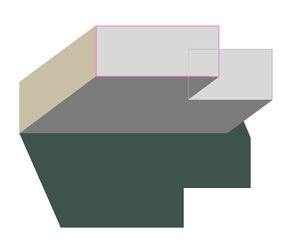
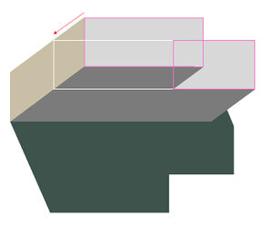
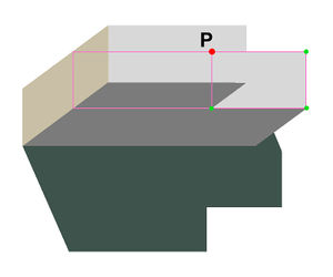
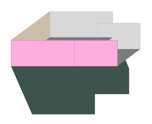
The correct tracing of buildings with different height components is particularly problematic. This is is especially true if the plan is also covered by adjacent buildings or trees. Sometimes only a tedious procedure as described below is possible.
1. The highest part of the building is drawn.
2. The traced outline is moved downward so that it touches the adjacent lower-lying area.
3. The area, which was traced first, usually gives us the location of additional, hidden points P that we need for construction of the second surface.
4. After tracing, the two areas are merged and moved down based on a visible corner of the floor plan.
Моделювання будівель розташованних на схилах
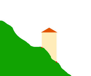
If a building stands on very uneven terrain,
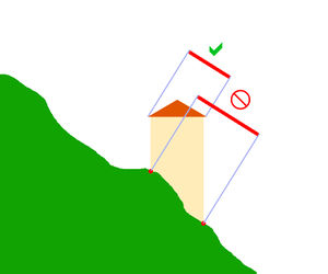
tracing the outlines of the buildings at the ground level leads to erroneous results, if used as a template for oblique aerial photographs:
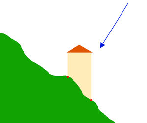 Blue arrow: View direction of the camera.
In such cases only the roof shape should be drawn as the building outline and not the geometry of the intersection lines between the building outline and terrain:
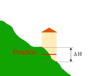
After construction of roof outlines, move them so that the building is properly placed in relationship to the street.
In case of free-standing buildings without reference to the street, the position error is reduced by a shift of half the distance between the lowest and highest position one as the outline for on the aerial photograph visible corner building on the site selected.
Моделювання будівель з використанням аерофото низької роздільної здатності
If in the background of OSM there are only roughly detailed aerial photographs, the tracing of the buildings is difficult because the size of the building is nearly the size asthe icons of the design tools. This is of the greatest difficulty, if one wants to draw precisely: The graphical representation of the tools and nodes is simply too large for the objects in the small scale. The approach described here deals with this problem in rectangular buildings. The technique is laborious and slow, but gives relatively good results.
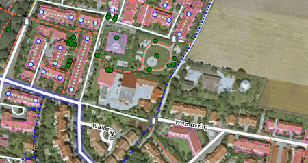 - Traced, the L-shaped building in the middle.
In the first step, a long construction line is drawn which is parallel to the longest visible wall of the building. The line should be longer than the building. This allows better assessment of the building orientation.
Draw a second construction line parallel to the first (Potlatch2 shortcut "P" )
At the ends of the two parallel lines a straight line is drawn which connects the two endpoints of the lines. The line is perpendicular to both vectors previously drawn.
Use button "create parallel way" and draw another (necessarily for construction) lines perpendicular to the first two lines drawn and placed at the outer edges of the building.
Additional long construction line in the middle is drawn:
At points where the lines intersect with each other, nodes are added.
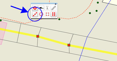
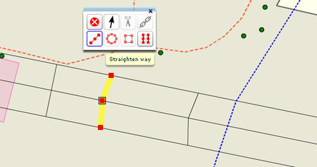
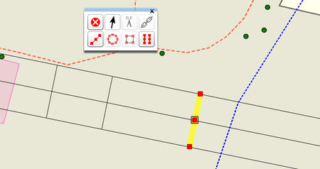
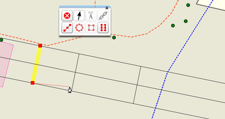
With the tool "straight way" one line must be straightened after the other ... (a weakness of the potlatch is a slight displacement of the points which we have added to the nodes on the paths)
When all lines straightend, you can start drawing the outline of the building:
Result:
Корегування помилок геометричної перспективи
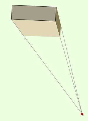
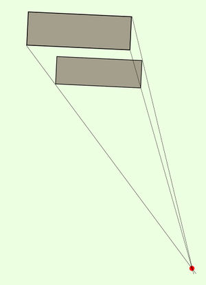
On the buildings on aerial photographs from low altitude (usually higher resolution) perspective distortion is often seen. This means that the correctly-drawn outline of the roof is larger than the building outline.
At first glance, you hardly notice this:
Only the tracing of corresponding vertical outside edges of the perspective view (reduction to the ground plan) would make this visible:
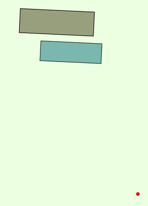
Since the building roof and floor plans are similar, you can use the tool "create parallel way" to create the right plan.
Practical approach:
- Trace roofline
- The roof outline is moved to the ground plan
- A matching corner (on this picture the lower left corner of the drawn polygon), is placed correctly on the aerial photograph.
- A construction line parallel to the (right image in this example) the outer edge of the building is drawn and placed on the outside edge of building on the aerial photograph:
The outline polygon is drawn smaller with the "create parallel way" tool:
Thus, the degree of reduction is clearly visible, the detail being greatly magnified.
(Therefore, the temporary construction line is shown, at higher zoom levels the detail image disappears).
- The newly drawn (except this picture right) outer edge of the polygon is copied
to lie on the half-way between the construction line and the source polygon.
- The original polygon and line construction is deleted, and the new plan polygon shifted to the right place.
Result:
Attention! This method is an approximation. You get absolut accurate results only by construction of the central perspective:
Коригування наслідків помилок при об'єднанні зображень
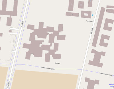
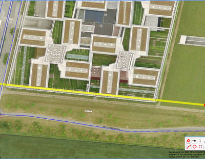
Bei dem Auswahl des Blickwinkels für Teile der Luftbilder von Bing war anscheinend die Sichtbarkeit der Straßen vom Vorrang. Um das zu erreichen müssen Ausschnitte der Luftbilder die aus verschiedenen Blickwinkel gemacht wurden zusammen gefügt werden. Daher passiert es, dass in manchen Bereichen in Bing Bilder das Dach eines Gebäudes aus nicht zusammenhängenden Teilen besteht:
Glücklicherweise sind solche Bilder aus großer Entfernung gemacht und meistens ist auch die Bodenebene richtig entzerrt, so dass wir annehmen können dass wir mit einer [[ http://de.wikipedia.org/wiki/Parallelprojektion%7CParallelprojektion]] zu tun haben. Deswegen können einzelne Dachteile einzeln modelliert und in der Bodeebene zusammengefügt werden.
Steps:
- Draw the construction lines of the first part of roof. Make the construction lines a little bit longer
- Move the construction lines in the ground level.
- Draw the construction lines of the second part of roof.
- Move the second group of construction lines in the ground level:
You see that the both groups of construction lines overlap, so You can connect them to an area
результат:
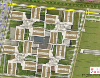
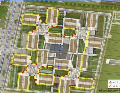
Моделювання великих поверхонь з викорстанням растру
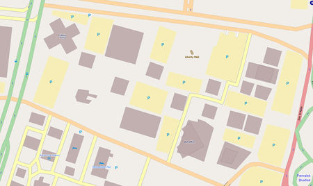
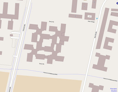
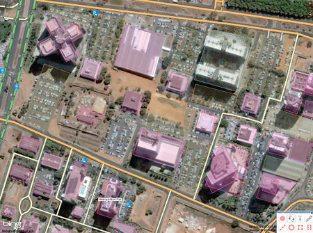 Existing OSM map - drawn without raster.
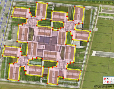
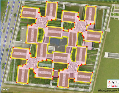
The city planners use in the planning often a grid: It makes planning and realization of construction projects in big areas easier. The persecution of the intentions of developers, due to the reconstruction of the main construction grid helps with tracing of buildings, roads and parking lots. In this way one avoids the inaccuracy that arises when one works only with short construction lines. The redrawn maps look even more professional: People recognize with the eyes slight deviations from parallelism of the lines (some people perceive the little difference of 0.5 °!)
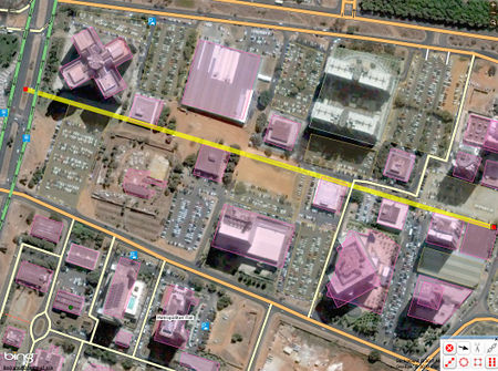 First construction step: Identification and drawing of construction axis. A question of practice:The longer the more reliable.
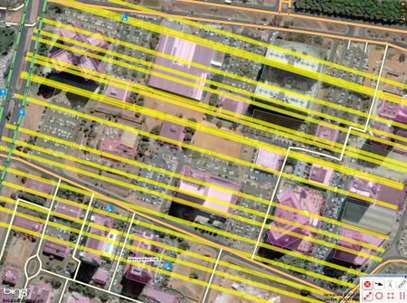 The axis should be multiplied to constructively relevant bodies (roads, building edges), etc.
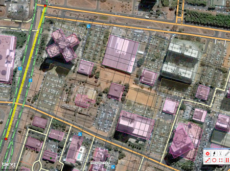 Analogously to the previous step: drawing of axis perpendicular to the first construction axis..
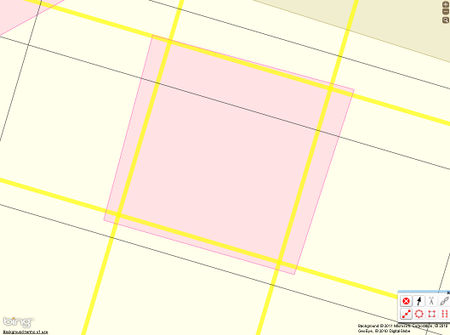 We see all the inaccuracies when zooming.
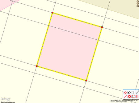 The inaccuracies will be corrected
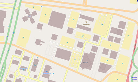
Result after correction.
In the upper left corner of the picture below we see a building at the cross plan. This building was also drawn more precisely by using of construction raster ( due to a rotation of 45 ° to the construction grid).
Використання ліній растру з допоміжними точками
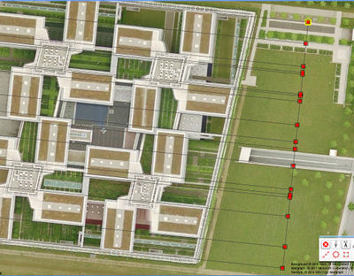
The technique described in the previous section is difficult, because You need to put manually at every point where two construction lines intersect an auxiliary point, or try to reach the intersection point of both lines at high zoom level.
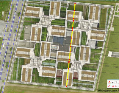
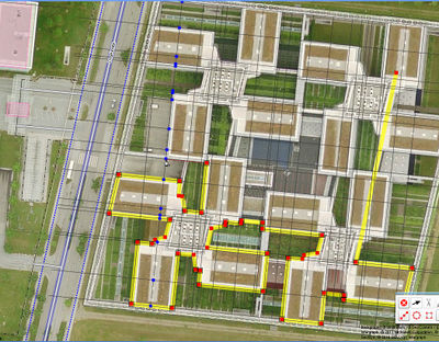
It is smarter, after drawing of all construction lines with one direction, to draw the first "vertical" line with all intersection points. After drawing of this line, simply mulitiply them at all necessarily places and use for drawing of building outline.
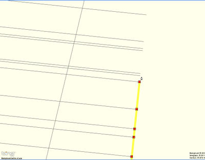 Begin with the first vertical construction line
