Tag:waterway=pressurised
| Description |
|---|
| An artificial waterway where water flows in a closed space without air |
| Group: waterways |
| Used on these elements |
| Useful combination |
| Status: approved |
| Tools for this tag |
|
The waterway=pressurised key maps artificial conduits where water flows in a permanently closed space, without air. As water is filling all space available, it applies a positive static pressure on the conduit walls.
The conduit can be either a pipeline or a tunnel. This is specified by adding man_made=pipeline or tunnel=* to the way tagged waterway=pressurised.
Pressurised waterways require an intake below the water level at all time as to prevent any air to get inside the conduit. It's not only a physical constraint but air can cause heavy damages on equipment expected to run with no air. There is usually no change in flowing regime as pressurised waterways require special design to run.
A "pipe flow regime" is one of the three main flow regimes of liquid water. This regime is obtained by design when the intake of the conduit is built below the lowest water level the source can reach.
How to map
Waterways are mapped as ways: draw a line, starting at the intake, in the direction of the flow of water. Tag with waterway=pressurised. Then, add man_made=pipeline, tunnel=culvert or tunnel=flooded depending of the nature of the conduit. Look at those keys pages for more information. Remember that the water conduit must start at an intake placed below water level.
Pressurised waterways can be added as a member of Relation:waterway with the role side_stream or main_stream depending of the situation.
There is actually no problem to use pressurised consecutively with any other waterway=* value depending of successive regimes found along the watercourse.
Usage
Such waterways are found in water transmission, irrigation and hydropower systems which need large amount of water. This is specified with an optional usage=* with one of the values:
Examples
Headraces
| Photo | Tagging | Note |
|---|---|---|
 |
waterway=pressurised
|
Horizontal tunnels carrying water from intakes to penstocks. Such ways have a pipe flow regime, their inlet are always below the water level and no air can get inside. |
 |
waterway=pressurised
|
The most complete case with a headrace pipeline hosted in a human accessible tunnel in operation. This is the only situation where man_made=pipeline is used in combination with tunnel=* on the same way. |
 |
On all parts, use: waterway=pressurised
operator=* On the bridge part, use:
On the underground part, use:
|
A big siphon allowing water to cross a valley. Only half side is visible on the picture, tunnels or pipelines are connecting each side at equivalent altitudes. The siphon is a pipe flow waterway. |
Penstocks
| Photo | Tagging | Note |
|---|---|---|
|
waterway=pressurised
|
Metallic penstocks feeding a power plant down the mountain. No air can get inside and water goes pipe flow | |
 |
waterway=pressurised
|
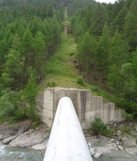
Vertical or inclined pressure shafts are shielded as pipeline without tubes. Pipes are connected upstream and downstream.
See the two vertical shafts on the power plant digital model and some pics of how it was built with a raise drill machine.
|

