Test the accuracy of GPS devices
Accuracy and integrity
- Accuracy is the deviation of measurement data of real actuality. At GPS-devices it is the deviation of the coordinate shown by the device from the 'correct' coordinate. Required are both coordinates being recorded in the same system (WGS-84 at OSM), respectively the accurate conversion of the coordinate when the reference value comes from another system.
- Availability is the complete and unmodified arrival of the data on the recipient.
- Reliability is a percentage describing the expected length of a system being able to execute an intended function with the required accuracy.
- Integrity is the ability of a system to inform the user early enough when not to being used anymore (wrong or missing measured values).
Accuracy of data
The accuracy depends on:
- quality of satellites
- disturbance at transmission until reception
- properties of reception devices (hard- and software)
The accuracy of the device depends on:
- quality of GPS-chip
- quality of electric signal processing
- quality of software
The producers of consumer-devices mostly don't give any information on the used hard- and software. Details on signal correction ("WAAS" etc.) are often indefinite to misleading. Also, the displayed "accuracy" of some devices is not defined and therefore rather useless.
Testing the device oneself
For that purpose you need an exactly known reference point on the free field. If you are lucky there is a measurement point with all around free sight to the sky and you get the exact coordinates. Or you ask a measurement engineer at a building lot whether he could determine a measurement point with all around sight to the sky for you, for example at a country road or a country lane (mostly he is gladly to do that). Then you can measure that point several times with your device and compare the middled result with the official coordinate.
Measuring the reference point
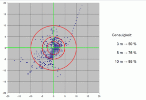
A single measurement of a point through a consumer-GPS-device is imprecise. The deviations add up to several dozen meters. Through multiple measurements (scatter-plots) and EGNOS improvements are possible. The best results are gained through differential-GPS-devices, but they are substantially more expensive.
Exact reference points can aso be created with long-term measurements. Therefore you need an exact determinable point on free field with free sight to sky:
The horizon should be lower than 10..20° and especially free to the South so that the EGNOS-satellites are better visible.
| Satellite | PRN | ID | Position | Direction | right-pointing | Elev. in Germany | Comment |
|---|---|---|---|---|---|---|---|
| Inmarsat AOR-E | 120 | 33 | Atlantic | 15,5° W | 195,5° | 25..30° | |
| ARTEMIS | 124 | 37 | Africa | 21,5° E | 158,5° | ||
| Inmarsat IOR-W | 126 | 39 | Africa | 25,0° E | 155° | currently testing system | |
| Sirius 5 | 5,0° E | 175° | since end of 2011 |
Simple method
If your device has a mode for just saving a point every minutes (some devices do that automatically if they are not moved), then you can simply lay the device on the reference point and get it back after 10 hours (as long as the battery works). From the logfile you calculate the mean value. With that you middled out any satellite- and weather-anomalies and get (on the free field) a submeter-exact position.
Complicated method
If your device has no minute-mode you can get a similarly exact result by measuring several points at several moments and then calculating the average value.
Mark a view points on a free area (or a plan of it) that are a few dozen meters away from each other and can be found again without a doubt at any moment. Suitable "callibration areas" are: big parking areas with drains, beach at a danish North Sea coast with residual bunkers, sports fields with solid markers, for example tennis, etc.
Measure the distances between all points (triangles) with a measuring tape or laser distance measurer.
- Measurement with GPS
Determine the positions of these points with your GPS: Fasten the device motionless for at least one minute at each point. Repeat the measurement ten times in the interval of at least 90 minutes to have different satellite constellations and possibly different atmospharical conditions. So for such an attempt you need 15 hours.
Calculate the average of each scatter-plot:
- Sum LAT / number of points in scatter-plot = LAT[average]
- Sum LON / number of points in scatter-plot = LON[average]
Some GPS-devices have a built-in function for that. Alternatively, log in save as spreadsheet and let it calculate automatically.
If you want to know it exactly, do 20 measurements on respectively only half of the points. That excludes a possible regular mistake whereby all measurement values could be shifted in the same direction through long-term atmospheric disturbances.
- Correction of Measured Values
- At the start of a measurement and sometimes at the end the device draws "wrong" points (for example residual movements, power-up-mistakes, satellite-search-mistakes). These can be determined well through statistic-programs and/or graphical displays. Such systematic mistakes can then be deleted from the series of measurement.
- Calculation
- Calculate the distances out of coordinate differences between a two reference points (or tap them in an editor)
- Determine the difference between measured and calculated distance
- Calculate the average difference: count all differences together and divide them through their quantity.
The result is a proportion for the maximal total accuracy of the device and environmental influences under good conditions. If the environmental influences decline the accuracy also declines. See Accuracy of GPS data ten times per minute in an interval of 90 minutes. Calculate the average of the scatter-plot.
You can also measure several points and middle the middle of every scatter-plot to an even more exact reference point:
- Sum LAT[Middle] / number of observations = LAT[total]
- Sum LON[Middle] / number of observations = LON[total]
Reference Points for Aerial Images
To check the georeferencing of aerial images, respectively to correctly shift not exactly georeferenced aerial images in JOSM, you need exactly measured reference points on the terrain. Requirement: the point needs to be exactly recognisable on the aerial image.
Reference points of others
Measurement points are ideal. You get them at the local government, at the building authority, at the land surveying office or any surveyor at your place (just ask). Such points are accurately on a centimeter-scale. You need the coordinate in WGS-84 (or you have to translate convert it) and also the height in WGS-84 (here the conversion is more complex).
Determine the reference point on your own
To position satellite images exactly you can calibrate reference points on your own. Look for points in the terrain that
- a) have as free sight as possible to the sky
- b) are highly visible at the aerial image
Measure the point with the GPS-device as described above.
Well suited are manhole covers, road markings and traffic islands, because they are well visible on the aerial image.
Choosing OSM nodes and POI as reference points
It is even better if you choose an object that exists on the ground and is of common public interest regardless of this measurement. You may also add the below keys on the said object as well (accuracy=*). Ensure that dense vegetation does not cover the object, or at least it should be clearly visible in months without foliage.
Surface
Midpoint:
Corners:
- leisure=pitch
- playground=sandpit
- amenity=parking_space, especially with ones having extra marking like parking_space=disabled or parking_space=charging
Protruding
One needs to watch out to properly intersect the lean and the shadow on aerial imagery to arrive at the on the ground base point of the given object. Here are some low rise points where you can usually put your instrument on top at the midpoint:
- man_made=street_cabinet
- amenity=drinking_water
- emergency=fire_hydrant pillars
- advertising=* boards or small columns
- amenity=bench
- leisure=picnic_table
- amenity=waste_basket
- playground=* equipment
- sport=table_tennis table
Special measurement apparatus needed (for measuring and averaging out 3 or 4 points around the object):
Synthetic
We usually add tagless empty nodes as part of ways when micromapping. These points are not POI (points of public interest), but if you can find literally nothing else from above, you may also choose some of these. They can also be clearly inferred on the ground, hence we may also add measurements to their midpoints:
- midpoint of centerline at top and bottom end of highway=steps where it joins a footway
- midpoint of centerline at the two ends of a marked pedestrian highway=crossing where it joins the footway/sidewalk – this is usually the place where you can also add a kerb=* (a measurement would also be possible in the middle of the road if it has no connected path ways, but that is a lot more difficult to determine on the ground)
- midpoint of preferably linear traffic_calming=*
- some points within a linear barrier=* like barrier=cable_barrier, barrier=guard_rail, barrier=handrail
- some midpoints of the centerline of footway=sidewalk
Survey points in OSM
Load the ground control point in the OSM-DB with an editor and name it with:
man_made=survey_point
survey=ground_control_point
source=*
          survey           (for normal GPS-devices)
          egnos            (for EGNS-corrected signals)
          on_top           (for elevated recipients/antennas)
          differential     (for differantial GPS)
          official         (for purchased points)
note=*                   'position will change'
description=*          '1. Sieldeckel im Immenredder westlich der Kreuzung Grützmühlenweg/Immenstieg'
name=*                   GCP_Immenredder_001 (the name starts with GCP (for GroundControlPoint)
See also
- Accuracy of GPS data
- Genauigkeit von Koordinaten
- Umrechnung von GK in WGS-84
- Reliability of OSM Coordinates
- Koordinate
| ||||||||||||||||||||||||||||||||||


